Architecture
Understanding the cloth folding robot system design
System Architecture
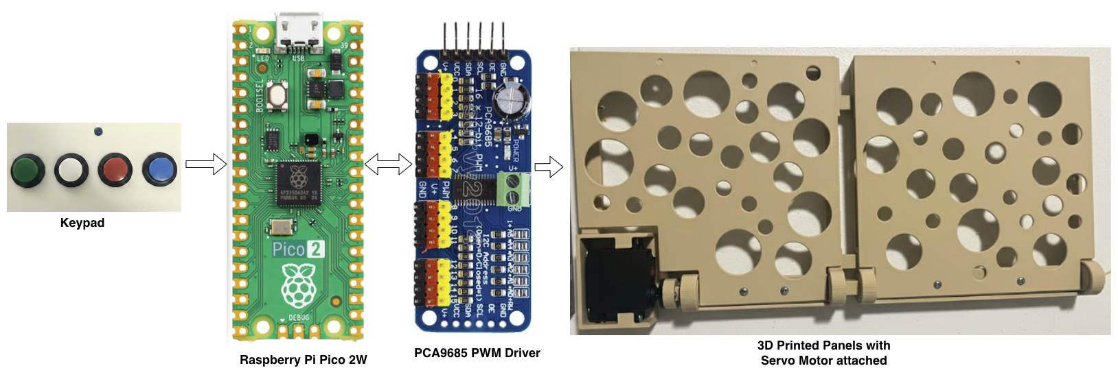
The Fabrica architecture is designed for modularity and scalability. It utilizes a Controller-Driver-Actuator pattern, allowing a low-power microcontroller to manage complex, multi-servo synchronized movements.
1. Hardware Layer
The hardware stack is divided into four functional segments:
Input Interface (Keypad)
A simple tactile interface for user triggers and "teaching" mode. The Pico 2W monitors these pins using internal pull-up resistors to detect state changes. Buttons use active-low configuration with 60ms debouncing to prevent false triggers.
Implementation: GPIO pins 2, 3, 4, 5 | Short press (<3s) = Execute | Long press (≥3s) = Record mode
Central Processing (Raspberry Pi Pico 2W)
The "brain" of the operation. It handles the state machine, manages I2C communication, and stores folding sequences in flash memory as JSON files.
Specs: Dual-core ARM Cortex-M33 @ 150MHz | 264KB SRAM | 4MB Flash | I2C @ 100kHz standard mode
Power & PWM Expansion (PCA9685)
Since the Pico cannot provide enough current or PWM pins for 16 servos, the PCA9685 acts as a bridge. It receives commands via I2C and provides 12-bit PWM resolution (4096 steps) to the servos at 50Hz.
I2C Address: 0x40 | PWM Range: 102 (0°) to 512 (180°) |Retries: Up to 3 attempts on I2C failure
Actuation (Servo Panels)
3D-printed hinges powered by high-torque servos. The modular design allows for "Follower" panels (mechanically linked) or "Motorized" panels (independently controlled). Each servo executes a fixed 3-step sequence: 0° → 180° (flip up), 180° → 10° (flip down), then 10° → 0° (slow return to prevent hard landing).
Movement Sequence: 600ms per 180° rotation | Soft Landing: 10° intermediate position prevents impact damage | Final Reset: All servos return to 0° home position after complete sequence
2. Communication Protocol
The system relies on the I2C (Inter-Integrated Circuit) bus for all primary control logic.
| Component | Protocol | Description |
|---|---|---|
| Pico ↔ PCA9685 | I2C | Sends 12-bit PWM duty cycle values and frequency (50Hz) to specific channels (0-15). Automatic retry logic with up to 3 attempts on communication failure. |
| Pico ↔ Keypad | GPIO (Digital) | Polling-based button detection with 60ms debouncing. Short press executes motion plan, long press (3+ seconds) enters configuration mode with LED blinking every 200ms. |
3. Software Architecture (MicroPython)
The software is built on a non-blocking execution model to allow for Parallel Motor Execution. The firmware uses polling-based event loops rather than interrupts to simplify logic and avoid race conditions.
A. The Motion Plan Executor
Unlike linear robots that move one motor at a time, Fabrica uses a step-based parallel execution system.
Data Structure: Motion plans are nested arrays of steps and channels:
[[0,1], [2,3]] = Step 1: Motors 0+1 parallel, then Step 2: Motors 2+3 parallel- Concurrency: Motors within a step execute in parallel. The system sends simultaneous PWM commands to multiple channels without waiting for completion.
- Sequential Steps: Each step completes before the next begins, ensuring controlled movement sequences. Fixed 600ms delay per 180° servo movement.
- Automatic Reset: After all steps complete, the executor resets all used motors to 0° home position for the next cycle.
B. The State Machine & Storage
Fabrica operates in distinct modes managed by a polling-based state machine:
Waiting for button input. LED off. System ready to execute stored sequences.
Teach mode activated by 3+ second button hold. LED blinks every 200ms. User presses buttons to build sequence steps. 5-second timeout saves current step. System records channel sequences to flash storage.
Short button press loads corresponding motion plan from storage and executes steps sequentially. LED indicates progress.
Persistent Storage: Motion plans stored in JSON format on the Pico's LittleFS filesystem. Default plans loaded from configuration on first boot. Changes persist across power cycles without reflashing firmware.
C. Error Handling & Reliability
- I2C Retry Logic: Up to 3 automatic retry attempts on communication failures with 10ms delays.
- Memory Management: Periodic garbage collection every 100 main loop iterations prevents memory fragmentation on constrained hardware (264KB RAM).
- Channel Validation: All motor indices checked against 0-15 range before I2C commands sent.
- LED Feedback: Visual indicators for startup (3 blinks), long press (blinking), and error states.
4. Modular Panel Logic
The system's scalability is achieved through a Grid Coordinate System. The code treats each motorized module as an independent object, making expansion straightforward.
Developers can define custom layouts through configuration files. Each motorized panel is assigned a channel on the PCA9685 (0–15). The standard 4×3 grid uses 12 channels (0-11), leaving 4 channels available for expansion. Because the system treats each panel as an independent object, expanding to different configurations requires only adding hardware and updating the channel mapping—the core movement logic remains unchanged.
Motion Plan Patterns
Motors activate one after another in order
Motors activate in reverse sequence
Motors work in synchronized pairs
All motors move simultaneously
Four pre-programmed motion plans mapped to buttons 0-3. Users can add unlimited patterns through "teach mode" without editing firmware.
Scalability
Minimum setup for testing. Channels 0-3 active.
Recommended standard configuration. Channels 0-11 mapped. Optimal for most garments.
Maximum capacity for large items. All PCA9685 channels utilized.
Motion plan logic automatically handles any configuration. No firmware changes needed—just update hardware connections and panel mappings through configuration.
5. Power Distribution Schema
Proper power sequencing is critical to prevent the Pico from resetting during high-torque maneuvers.
Logic Rail
5V/1A via USB or dedicated regulator for the Pico and PCA9685 logic.
Power Rail
5V-6V/10A+ (depending on motor count) connected to the PCA9685 power terminal.
Ground Plane
All components must share a common ground to ensure signal integrity on the I2C bus.