Raspberry Pi Pico Setup
Pin assignments and connections for the Raspberry Pi Pico 2W microcontroller
Watch this step-by-step guide on connecting and configuring the Raspberry Pi Pico 2W for the cloth folding robot.
About Raspberry Pi Pico 2W
The Raspberry Pi Pico 2W is the brain of Fabrica. It features the RP2350 dual-core ARM Cortex-M33 processor, built-in WiFi/Bluetooth, and ample GPIO pins for interfacing with buttons, LEDs, and I2C devices.
Key Specifications
- • RP2350 dual-core @ 150 MHz
- • 520 KB on-chip SRAM
- • WiFi 802.11n & Bluetooth 5.2
- • 26 GPIO pins (3.3V logic)
Our Usage
- • I2C communication (GP0, GP1)
- • 4 input buttons (GP2-GP5)
- • 1 status LED output (GP6)
- • Power distribution via VBUS/GND
GPIO Pin Assignments
⚠️ Important: 3.3V Logic Levels
The Raspberry Pi Pico operates at 3.3V logic. Do not connect 5V signals directly to GPIO pins. The PCA9685 is 5V-tolerant on I2C lines, making them compatible.
| Pin # | GPIO | Function | Connection | Notes |
|---|---|---|---|---|
| I2C Communication | ||||
| Pin 1 | GP0 | I2C0 SDA | PCA9685 SDA | Data line |
| Pin 2 | GP1 | I2C0 SCL | PCA9685 SCL | Clock line |
| Control Buttons (Active-Low, Pull-Up Enabled) | ||||
| Pin 4 | GP2 | Button 1 Input | Green Button | Motion Plan 1 |
| Pin 5 | GP3 | Button 2 Input | Blue Button | Motion Plan 2 |
| Pin 6 | GP4 | Button 3 Input | Yellow Button | Motion Plan 3 |
| Pin 7 | GP5 | Button 4 Input | Black Button | Motion Plan 4 |
| Status Indicator | ||||
| Pin 9 | GP6 | LED Output | Status LED (via resistor) | Programming mode indicator |
| Power Distribution | ||||
| Pin 36 | 3V3(OUT) | 3.3V Output | PCA9685 VCC (logic power) | Max 300mA total |
| Pin 40 | VBUS | 5V Input/Output | Optional: PCA9685 V+ (if USB powered) | 500mA max from USB |
| Pin 3, 38 | GND | Ground | Common ground (all components) | Multiple GND available |
Pico Pinout Reference
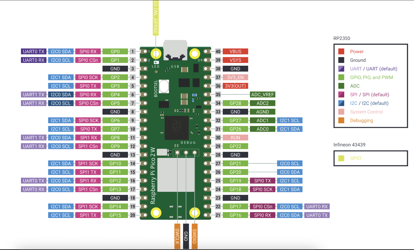
Physical Pin Numbers
Pin numbers are counted from top-left (Pin 1) going down the left side (1-20), then continuing at bottom-right (Pin 21) going up the right side (21-40).
GPIO Numbers
In code, we reference GPIO numbers (GP0-GP28), not physical pin numbers. Example: GP2 is on physical Pin 4.
Wiring Best Practices
✅ Recommended
- • Use color-coded wires for easy identification
- • Keep I2C wires short (<30cm) and twisted together
- • Use female-to-female jumper wires with headers
- • Label wires with tape or heat-shrink markers
- • Test continuity before powering up
❌ Avoid
- • Connecting 5V signals to GPIO inputs
- • Using power supply >5V for VBUS
- • Running I2C lines parallel to servo power cables
- • Forgetting common ground connections
- • Hot-swapping connections while powered
Code Configuration
Pin assignments are defined in config.py:
# I2C Configuration
I2C_CHANNEL = 0       # I2C bus number
SDA_PIN = 0           # GPIO 0 (Pin 1)
SCL_PIN = 1           # GPIO 1 (Pin 2)
I2C_FREQ = 100000     # 100 kHz

# Button Configuration
BUTTON_PINS = [2, 3, 4, 5]  # GP2-GP5

# LED Configuration
LED_PIN = 6           # GPIO 6 (Pin 9)

# PCA9685 Address
SERVO_CONTROLLER_ADDR = 0x40
Only modify these values if you change physical wiring or need different I2C addresses.